Your leaking thatched hut during the restoration of a pre-Enlightenment state.


Hello, my name is Judas Gutenberg and this is my blaag (pronounced as you would the vomit noise "hyroop-bleuach").


links

decay & ruin
Biosphere II
Chernobyl
dead malls
Detroit
Irving housing

got that wrong
Paleofuture.com

appropriate tech
Arduino μcontrollers
Backwoods Home
Fractal antenna

fun social media stuff


Like asecular.com
(nobody does!)

Like my brownhouse:
   installing Solar Controller III
Wednesday, February 23 2011
I spent most of the day installing the new solar controller (Solar Controller III) in the basement and gradually decommissioning the old one. The first step of the process was the most arduous: getting the controller to communicate effectively across its 100 feet of RS-232 serial cable. This would be essential, because it would allow me to quickly upload new firmware, which I would be able to tweak and elaborate from the comfort of my main computer (I can even use Homesite, my favorite text editor). Recent versions of the Arduino platform make such uploads painless by automatically resetting the board so that it can run the bootloader and look for new software should that be what is being sent. But none of this was designed to work across a 100 feet of serial cable; indeed, modern Arduinos all attach via USB, not serial, and the range of USB is much more restricted than even serial. Supposedly serial cables have a general limit of fifty feet, though (after much experimentation), I was eventually able to get a reliable connection to the basement for Solar Controller II, which allowed me to gradually elaborate a very comprehensive control platform, one that I could modify to accommodate other remote control scenarios. The main problem with the long serial cables is not so much with the reliability of the communications as it is with the triggering of Arduino's auto-reset feature, the thing that allows it to be remotely reflashed without fuss or bother. This triggering is caused by a capacitor placed between the RTS (Request to Send) pin and the Atmega's Reset pin. If the value of the capacitor is too large, the resets happen all the time (triggered, perhaps, by induced signals from the other wires in the cable). But if the value of the capacitor is too small, the resets never happen when they should. I find I can use fairly large capacitors (0.1 μF) when the cables are the short kind used to hook things up. But when the cables reach to the basement, the capacitors have to be in the 100 pF range. During today's installation, I quickly realized that this reset capacitor was going to have to be yet another socketed item on the controller's circuit board, because I was going to need to try a range of values before it was going to work. Coupled with this problem was another I hadn't realized: the cables I'd set up (I actually have two different serial cables running to the basement) were built to do their cable-induced resets using the data terminal ready (DTR) signal, not RTS. So I also had to change a jumper on the Olimex board (happily, it actually came with such a jumper). Eventually I was able to get reliable serial communications using the unshielded serial cable but not the shielded one. Go figure. After that, it was fairly easy to connect up a subset of the analog inputs and a few of the outputs, enough to get it working at a basic level.

For those who found this via a Google search and want to look at the firmware I've been working on, download it here. There's code in there for both the master and the slave Atmegas.


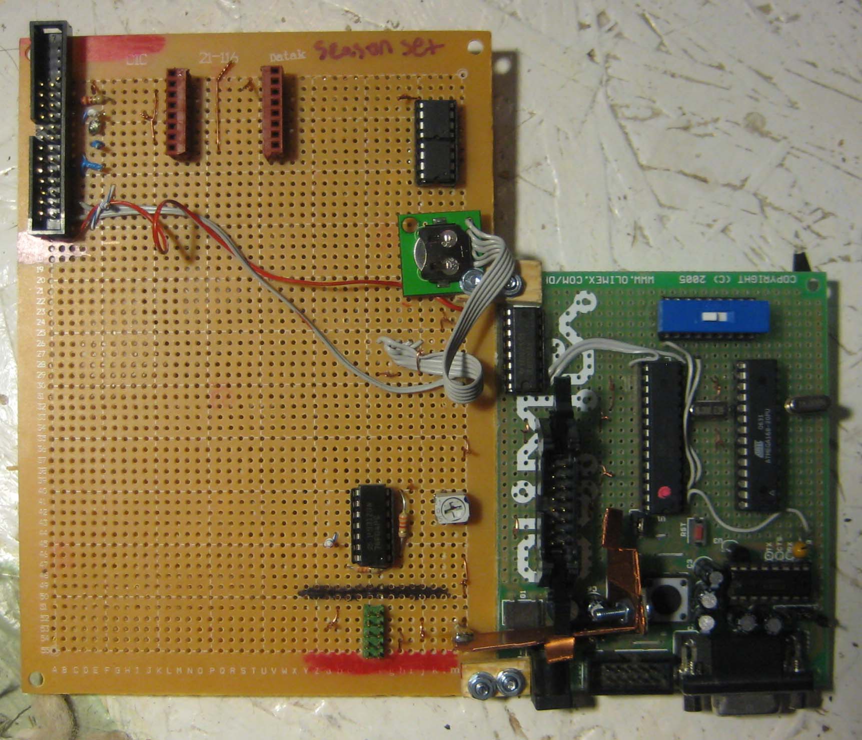
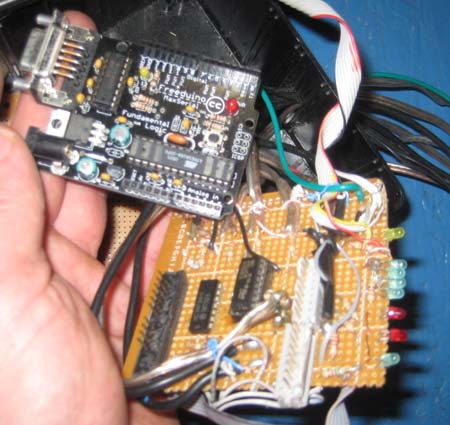
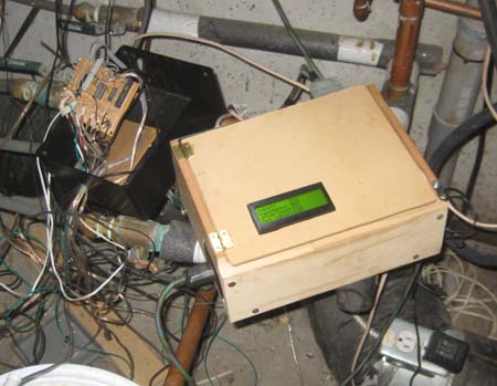
Solar Controller III as it looked a few days ago. Since then I have added some connectors to make it easier to deal with entirely from the topside. The two Atmegas are visible beneath the blue switch allowing me to switch the serial cable to connect to either one or the other. Click to enlarge.


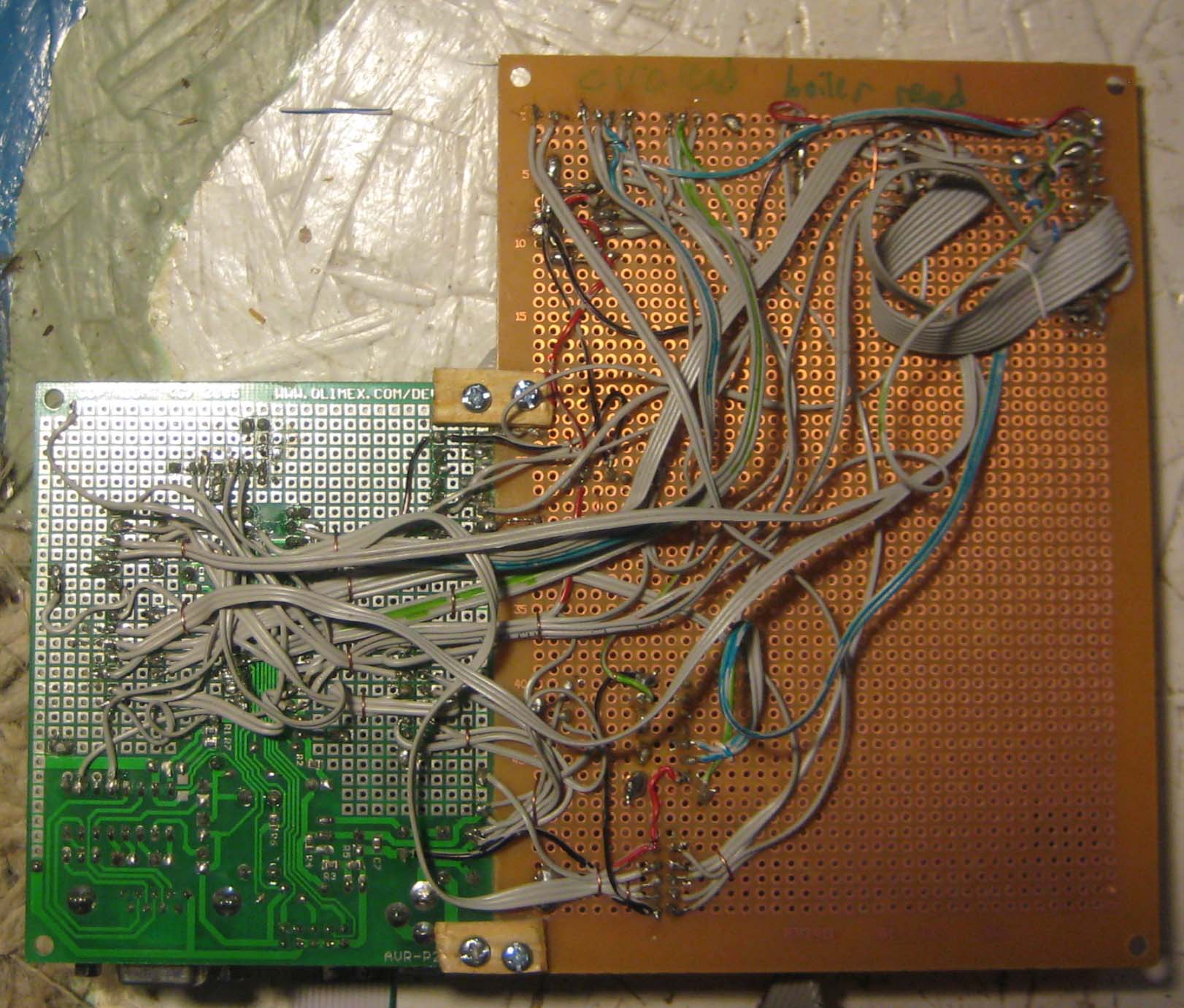
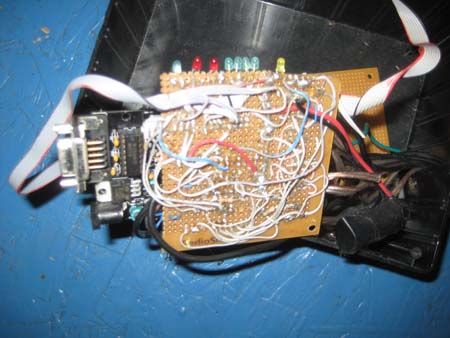
The bottom of Solar Controller III as it looked a few days ago. Click to enlarge.

now a walk down memory lane


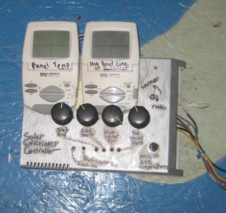
Solar Controller 0, which I'd forgotten I'd actually built, was the first calculator of solar sufficiency (fall, 2005). It used comparators and tiny potentiometers for tweaking temperature cut on and cut off.


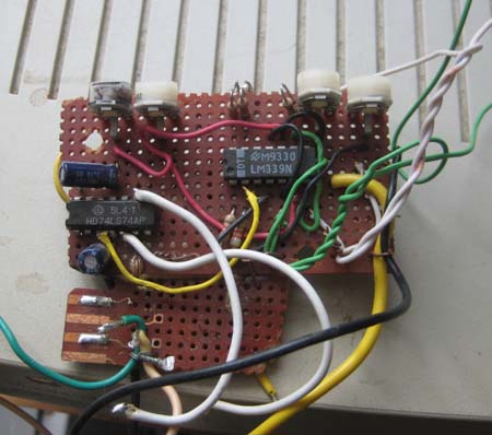
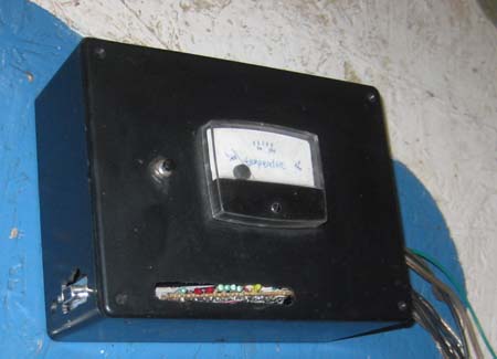
Solar Controller I, built in the fall of 2005. It uses mostly analog circuitry and a flip flop to determine solar sufficiency.


Solar Controller I, the way it looks inside. The relays allowed me to quickly switch the wires from the thermistors to the digital thermostats so I could read the temperatures on their displays -- though this made the controller blind to the sensors while I was looking.


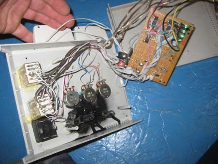
Solar Controller II, built mostly in late 2006, orginally based on an Arduino NG.


Later I replaced the Arduino NG with a Freeduino MaxSerial, which could finally communicate reliably with the laboratory.


The underside of Solar Controller II.


Solar Controller III as it looked during installation today. Solar Controller II is still partially-connected to the left.


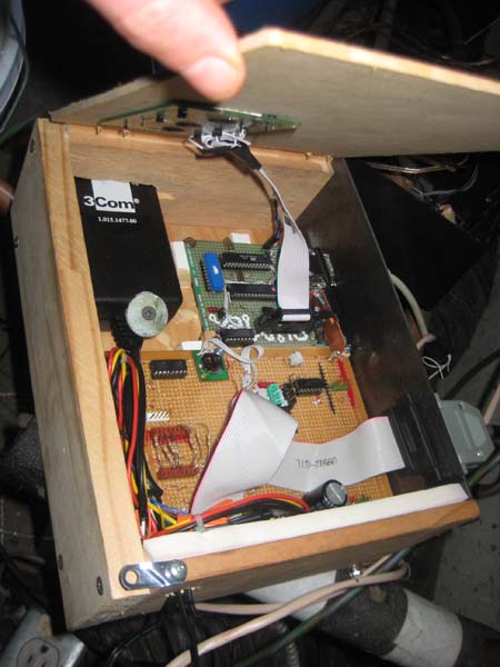
The beautiful insides of Solar Controller III. Note the power brick and the socketed resistors to use with different thermistors.


For linking purposes this article's URL is:
http://asecular.com/blog.php?110223

feedback
previous | next